The problems of suspension
Even the first bicycles from the previous century, the “boneshakers”, already had problems with comfort, as the name suggests. Designing suspension systems for bicycles is therefore not new. The American Bluell velocipede (1869) was already equipped with a kind of elliptical leaf springs. A good overview can be found on this website: https://onlinebicyclemuseum.co.uk/tour/spring-frames/ Especially in that time, when the wheels were made with iron rims with a strip of leather or rubber glued to them, this was not a luxury. In all designs from that period we see a floating saddle; the frame was also sometimes made with suspension. The lack of damping on most suspension systems made them not very popular; the production costs of these frames were higher and due to play in the bearings, the frame became weaker. The invention of the pneumatic tire meant the end of the sprung designs of that period.

The ideal suspension system absorbs the shocks of road imperfections and maintains contact between tire and road surface at all times. The operation of the suspension should not be affected by drive, brakes or weight load. Unfortunately, this is not technically possible: every suspension system is a compromise! Damping always costs energy and is therefore not used on racing bicycles. There have been experiments in Paris- Roubaix for example, but we don't see it anymore; conclusion: it didn't go any faster! In the ATB scene, suspension has been developped into a mature design, enhancing controll while decending.
However, there have been more suspension bicycles on the market. A successful design was the Moulton mini bicycle from the 1960s. Because small wheels pick up every pothole, this bike had suspension. In combination with high-pressure tires, this resulted in an easy-running and comfortable bicycle; unfortunately pricey. Success led to imitation; here they dispensed with suspension and started using thick low-pressure tires. The rolling resistance became enormous and the “mini bike craze” was over in no time. For traditional bicycle designs, suspension has disadvantages. The bottom bracket must be high to allow for suspension travel; otherwise the pedals will come to the ground too quickly. This makes it difficult to put your foot on the ground when stationary. Sometimes the rider is forced into a saddle position that is too low, which is at the expense of efficiency and cycling pleasure. Within the recumbent bicycle world, suspension is seen as necessary to actually utilize the potential of seating pleasure. KWB (short wheelbase) designs in particular are uncomfortable on cobblestone roads and poor cycle paths. Until the early 1990s, people often had to make do with rubber block suspension. Unfortunately, the damping was poor, which meant that annoying swaying was often unavoidable. The advent of suspension in ATB bicycles has only attracted interest from component manufacturers. There is currently a wide range of hydraulically damped suspension systems and forks. Recumbent cyclists also benefit from this. It is a misconception that the problems of suspension systems only apply to ATBs and that recumbent bicycles are not affected by them due to the forward-facing pedaling movement.
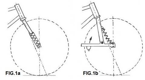
The telescopic fork (see FIG.1a) is popular among front forks. Every now and then there are designers who make something different: a rocking arm fork (FIG. 1b) or a deformable parallelogram with auxiliary fork (see FIG.1c) but it is difficult to compete against an established and good product.
An annoying phenomenon when braking is that there is more pressure on the front wheel. This causes the bicycle to dive into the suspension; the suspension is therefore already compressed and the spring action is zero. A design where the braking force counteracts this can be seen in the swing arm front fork design. There are several complicated designs on the market today; anti-dive is often the intended purpose; see the Motion front fork FIG.1e.


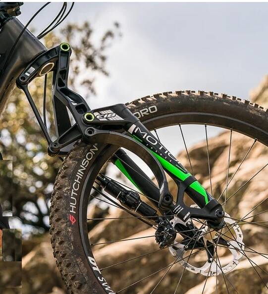
FIG.1c Girvin
FIG.1d Trust
FIG. 1e Motion carbon fiber leaf spring
With chainstays, things are much more complicated; No single concept can yet be identified as the winner here. The main cause of this is that the drive is usually via the rear wheel. One problem is that the cadence is almost equal to the natural frequency of the frame, which can cause interaction with the suspension system (bobbing); this phenomenon can also occur in the front fork. Choosing the right suspension is important for good road holding. During acceleration, the rear end will sink slightly into the springs, and during braking the fork will 'dive' into the springs. Springs therefore influence the balance, because they partly influence the weight distribution front and rear. The force that the rider exerts on the pedal, especially when accelerating, can be absorbed by the suspension. The rider then pumps his precious energy into the suspension system!
This doom-mongering has dominated rear suspension experiments for years. Mountain bikers demanded the ability to fix their suspension system during the climb (lock-out). Modern suspension systems often provide options to adapt damping and suspension to the terrain, sometimes even while riding. Improvements of the geometry have been made over the past decade. When pedaling, the center of gravity shifts. If the frequency of these shifts matches that of the rear suspension, this can introduce annoying rocking movements. (pedal bobbing).
If the pivot point of the rear fork is lower than the pulling chain, part of the pedaling energy can be absorbed by the suspension (see FIG. 2a). The first ATBs with rear suspension had a high pivot point. Unfortunately, this did not improve the stiffness of the rear frame. Furthermore, the chain pulled the rear wheel forward/down into the ground (see FIG. 2b). The suspension then hardly works anymore, because the impact of the pothole upwards must be greater than the force that the rider exerts downwards. This causes significant shocks on the pedals.
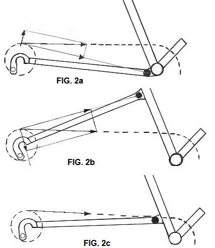
Nowadays the pivot point is lower, at the level of the middle chainring: ideally if the chainline runs through the pivot point (see FIG.2c). The braking force on our rear fork can also influence the suspension; the brake cams are often quite a distance from the pivot point and the braking force of the rear wheel can push the fork down. The suspension is then partially blocked. In some complicated suspension systems the pivot point moves during compression, e.g. at GT's I-drive.
There are four main constructions, but there are many variations. In the English that characterizes the ATB world, these are:
1.the “MacPherson strut”,
2.the “Unified rear triangle”,
3. the “Cantilever beam” and
4. the “Rising rate linkage”.

In the first construction, the pivot point is on the rear fork. The spring element with damper is located at the end of the seat stay. By using a HorstLink (pivot point) for the rear dropout, the suspension system will be reasonably active. If the pivot point of the rear fork is chosen correctly, the influence of the drive is minimal. The braking effect of V-brakes will result in lateral loading (and extra friction) in the damper, because the seat fork is pressed downwards. We hardly see this system in new designs anymore, although the disc brake has solved the problem. When braking, there was poor suspension performance; inconvenient on the descent when you need both functions. A disc brake or hub brake is highly recommended. There is little space in the top triangle. We often see an interrupted seat tube with this system. The transition to the cantilever beam is not always clearly indicated. With the unified rear triangle (FIG.3b), the rear fork and the bracket form a whole. The pedals are not sprung and the rider's weight is therefore partly unsprung. The location of the pivot point determines the extent to which braking and driving forces influence the operation of the suspension. Unless there are major construction limitations, I won't recommend it to anyone. The cantilever beam (FIG.3c) is the favorite for recumbent bicycles. A simple system, which, provided the pivot point is chosen at the middle chainring, is fairly independent of the rider's strength. With a large leaf, the upward force will be slightly positive, which improves the response of the suspension; nice on the descent. With the small blade the suspension will stiffen slightly; nice in the climb. The braking effect has little influence. Even a high-tech company like Cannondale released a cantilever beam in 2006 with the Rush suspension system.
The only objection to the rising rate linkage (FIG.3d) is that this construction has a minimum of three pivot points. This is more complicated, but the technical capabilities of this system are far superior to other concepts. With conventional suspension systems, the spring element will be compressed directly proportional to the displacement of the rear axle; when we get to the end of the spring, that movement is limited very quickly. By choosing pivot points 2 and 3, we can select this for the “Rising rate linkage”. The dimensions between pivot points 2 and 3, and from point 3 to the upper mounting of the spring element, determine the movement of the rear axle. What is very nice about this is that the turning circle of the upper mounting point in the first part of the stroke has an amplification factor of, for example, 2:1, i.e. 2 cm movement of the rear axle gives 1 cm of compression of the suspension. In the lower part of the stroke, the spring will be compressed very little by the rotating movement of the short arm. Pressing half a centimeter can then mean 2cm of movement for the rear axle: 4:1. The properties of this design fit well with air suspension.
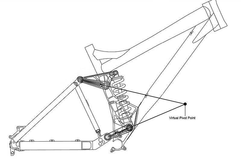
FIG.3e The DW-link ( Wikipedia)

FIG.3f Whyte made full suspension bikes.
Experiments with various constructions according to this principle show that it is possible to virtually eliminate the main technical problems such as braking effect and pedal force. However, one or two additional pivot points are often chosen. A solution to the force of V-brakes is to ensure that this force is parallel to the line through pivot points 2 and 3. As a result, the reaction force will be transmitted directly to pivot point 3 on the frame; the suspension is then not affected (it does not matter with disc brakes). There are four-point constructions (parallelogram or trapezoid) in which the wheel compresses parallel to the bottom bracket: this eliminates the driving force, including with Giant's NRS system. The DW-link (FIG.3e) of the late 1990s in the USA was an inspiration for these designs, and has led to some patent problems for Giant. With Giant's Maestro system (see video below), the pivot point of the rear axle moved during compression; this also happened with GT's i-Drive. A virtual pivot point is created that keeps the chain length virtually the same over the entire suspension travel.
Well, that's how it can be. There are several manufacturers who have designed a similarly complicated front frame/fork construction. The front fork easily includes three or four bearings. As for stiffness and clearance, not always a good choice. Of course this also drives up prices. The implementation of the various pivot points does not always have to cause technical problems. After all, we have been building motorcycles with similar constructions and much higher loads for decades. There are of course choices to be made regarding the design of the bearing. Low friction in the bearing is not our main concern; the movement of the bearing is usually limited to a rotation of a few tens of degrees. There are many ATB brands that opt for rolling bearings, often needle bearings to absorb the radial forces in combination with ball thrust bearings to absorb the axial forces; To me the choice of rolling bearings seems exaggerated. The only advantage is that it responds more quickly to small bumps, but then the spring and damper must also have this property.
The usual solutions in engineering for bearings in these types of constructions are the bushing for radial forces and collar bearings for the axial forces. Bearing bushes and collar bearings made of nylon or Teflon are actually not strong and wear-resistant enough for our purposes. The simplest bearing bushes are made of bronze and must be lubricated via a grease nipple. There are also self-lubricating bearing bushes; carbon particles have been added to the bronze, which are saturated with oil. There are even good qualities of unlubricated bearing bushes. These consist of a thin steel jacket with a longitudinal slit. The steel jacket has a layer of bronze with a Teflon coating. For a shaft with a diameter of 10-20 mm, the wall thickness of the bearing bush is 1 to 1.5 mm (e.g. INA Permaglide). The whole thing must fit well; play in the bearing is disastrous for the driving characteristics. Too tight a fit will cause rapid wear. A good and simple bearing construction consists of two Permaglide collar bearings with a high-quality stainless steel bolt (minimum M10 class 8.8, with heavy loads M12 class 12.8).
Springs
We can choose from: 1. suspension systems with gas (air) as a spring medium 2. steel springs 3. elastomers (rubbers or plastic foam materials) 4. carbon leaf springs. 1. Air springs have the advantages of light weight and good return. They have progressive compression, which means that at the end of the stroke more and more force is required for a little suspension travel; Furthermore, the construction is expensive due to the high quality of the seals required. 2. Steel springs have linear compression, they are quite heavy and will "punch out" in the event of a large impact. A certain force is required to compress a coil spring. The force required to compress a spring is directly proportional to the change in length. A greater force on the spring therefore results in a greater change in length. As a formula: force = change in length x spring constant. A large spring rate therefore represents a stiff spring, and a small spring rate represents a weak spring. If the spring constant is chosen too small, the spring will "punch" (metal on metal). 3. Elastomers are light and cheap, but their performance is temperature dependent, they harden quickly due to aging and the recovery is poor. They have self-damping properties, which can be optimized by the choice of material (e.g. alternating foam and rubber). The lifespan is very limited; suspension travel and damping deteriorate quickly. 4. Carbon leaf springs are used in some recent fork constructions, see the Motion in FIG.1e.
By the way, more than 10 years ago, the American Eagle Lightning already used a carbon/titanium chainstay as a leaf spring. The front fork of my old Moulton (1964) has a spring with a loose rubber rod in it. When compressed, that rod will expand; the steel spring and rubber absorb the impact. The friction of the rubber against the steel spring provides damping. This construction still works fine after 45 years.
Damping
Damping is necessary to absorb the energy of the shocks; without damping the bike will bounce. Springs will 'store' energy when compressing and release it when springing out. The damping ensures that excess energy is absorbed. We don't see many mechanical dampers based on friction anymore. Today it is the oil-filled hydraulic dampers that dominate the market. With a good damper, you can adjust the speed (of the damper rod relative to the housing) at which the dampers rebound. The viscosity (fluidity) of the damper oil and the size or number of the openings in the piston determine the properties of the damping. A liquid (just like gases) can flow in two ways; laminar and turbulent. A turbulent flow requires more energy because there is more friction in the fluid; see also the fluid mechanics page on this site: aerodynamics.
When the damper rod is pressed slowly, the damper oil will flow laminarly through the holes in the piston. If the speed of the piston rod is high, the damper oil will flow turbulently through the holes of the piston. As long as the flow is laminar, the resistance caused by the piston is directly proportional to the speed of the piston rod. The moment the flow changes to turbulent, the resistance increases considerably. It seems as if the piston is getting stuck in the oil. This effect can keep your bike's springs from "punching metal on metal" when you land after jumping off a bump, but it can also cause your bike to bounce when you ride over cobblestones at high speed. The right choice of damper oil and piston is therefore important; a piston with small holes and light damper oil (low viscosity), or a piston with large or multiple holes with heavy damper oil (high viscosity) will have the same effect for low speed damping. At high speed, the first mentioned combination will seize quickly due to the high flow speed of the thin damper oil through a small hole. With the second combination, the piston will only lock at much higher damper speeds, or not at all, because the flow rate of the damper oil is a lot lower (larger holes), and the higher internal friction of the damper oil absorbs more energy. Increasing the temperature will decrease the viscosity and change the properties of the damper.
It is possible to control damper oil via modern electronics. Speed sensors can then control valves that make the openings in the piston larger or smaller. This variable can also be included in the damping process via a connection to a temperature sensor. These types of systems are of course expensive, but will certainly be used more in the future.
The company Motion Instruments has created a measuring system that transmits the suspension data to an app on the iPhone. This allows you to see for yourself the results of changing your "set up", the setting of your suspension. Optimization with real measurement results as a background. https://motioninstruments.com/ . This way you can experiment and adapt your bike to your own values and preferences.
Extra info: pdf SRAM . video TREK . https://accutuneoffroad.com/articles/ , and on YouTube: